
PMC White Papers | MODELING OF CHAIN CONVEYORS AND THEIR EQUIPMENT INTERFACES
January 3, 2023
PMC White Papers | MODELING OF CHAIN CONVEYORS AND THEIR EQUIPMENT INTERFACES

danielg |
MODELING OF CHAIN CONVEYORS AND THEIR EQUIPMENT INTERFACES
Ali K. Gunal
Shigeru Sadakane
Production Modeling Corporation
Three Parklane Boulevard, Suite 910 West
Dearborn, Michigan 48126, U.S.A.
Edward J. Williams
206-2 Engineering Computer Center, Mail Drop 3
Ford Motor Company
Dearborn, Michigan 48121-2053, U.S.A.
Copyright held by, and to appear in, Proceedings of the 1996 Winter Simulation Conference.
ABSTRACT
Chain conveyors are a specific type of conveyor often used in a variety of manufacturing and production applications, such as body and paint shops. These conveyors must typically interface with other types of conveyors such as cross-transfer conveyors, and also with other material-handling equipment such as lift tables and hold tables. Micromodeling of chain conveyors and their equipment interfaces requires close attention to numerous details. These details include not only static and operational properties of the chain conveyors themselves, but also the particulars of dimensional and operational interfaces of the conveyors and the equipment served by the conveyors, such as lift tables and the conveyor acceleration and deceleration ramps.
In this paper, we first delineate the situations in which micromodeling of material-handling equipment is appropriate. We then present an overview of conveyor types and terminology. Next, we describe the challenges of modeling chain conveyors accurately, and our recommendations for meeting these challenges within the framework of typical modeling tools and simulation-study contexts. As an example, we present details of these recommendations relative to the AutoMod modeling tool. In conclusion, we summarize these recommendations and indicate promising directions for further development of modeling techniques and enhancement of model-building tools.
1 MACRO- VS. MICRO-MODELING
Macro models are, by definition, overview models with a “coarse” level of detail. In contrast, micro models incorporate a “fine” (high) level of detail (Ülgen, Shore, and Grajo 1994). The appropriate level of detail for a particular model within a simulation study, and hence the decision of whether to build a macro or a micro model, properly depends on the objectives of the study, availability of data, credibility concerns, and constraints of model-development and computer-run time available (Law and McComas 1991). In view of this credibility concern, the modeler making the “micro model versus macro model” decision properly anticipates the task of validation by asking “Will our modeling team be able to use the model – in place of the system – to make the decisions required by the study objectives?” (Ruch and Kellert 1995).
Simulation may be applied to the study of material handling systems during any or all of four project phases: the conceptual phase, the detailed design phase, the launching phase, and the fully-operational phase (Ülgen and Upendram 1995). In the context of modeling material-handling systems, typical indications calling for development of a micromodel are requirements to minimize both global and local work-in-process levels and maximize utilization of material-handling equipment, plus availability of detailed dimensional, cycle-time, and downtime data relative to individual pieces of equipment, such as the aerial gravity conveyors and motorized roller conveyors compared in (Cerda 1995). Such modeling is frequently required due to the mathematical intractibility of operational questions involving material-handling equipment. For example, (Tsai 1995) verifies the “NP-hard” status of minimizing the likelihood of conveyor stoppage to complete assembly-station work, via mixed-model sequencing, when a conveyor serves even a single station with arbitrary processing times. In such a context, detailed modeling of conveyors becomes vital to address decision-making policy relative to both line balancing and product sequencing. The motivation to model conveyors, in particular, at a high level of detail increases in studies undertaken to assess competing conveyor management strategies, such as dynamic allocation of workpieces to conveyors which alternately merge with each other, diverge again, and must serve widely dispersed, dissimilar work cells (Laughery 1995). Macro models are frequently analyzed to optimize conveyor and overall system performance via selection of a workpiece to convey, selection of a conveyor, choice of waiting discipline among conveyors, or choice of waiting discipline among jobs awaiting a conveyor. Micro models of conveyor performance furnish required input to such macro models (Backers and Steffens 1983).
2 DEFINITIONS AND TERMINOLOGY OF CONVEYORS AND INTERFACE EQUIPMENT
Conveyors can transport a high volume of items over a fixed path at adjustable speed with little manual intervention. Many varieties of conveyors are in use, such as belt conveyors (endless belt), chute conveyors (metal slides), screw conveyors (large spiral contained in confining trough or tube), chain conveyors (endless chain), and roller conveyors (load carried on transverse rollers which are either gravity- or power-driven) (Sule 1988). For example, belt or roller conveyors can be readily configured to transport small, odd-shaped items (Gould 1994). Chain-driven conveyors with roller surfaces, the type of conveyor considered in this paper, are occasionally non-powered (gravity) or, more usually, powered (live). Such conveyors are relatively inexpensive, readily assembled and adjusted, and well suited for a wide range of loads, provided the materials being transported have, or are mounted on, a rigid riding surface (Allegri 1992). These chain-driven conveyors may accumulate material by use of slip or clutch mechanisms built into the rollers. The “roller flight” variety typically uses two parallel sections of chain supporting rollers on non-rotating shafts. Those rollers can turn under the material, permitting its accumulation (Gould 1993). Additionally, acceleration and deceleration sections may be appended to powered roller conveyors when precise material control is required, as at interface points, through inclines or declines, or around curves (K. W. Tunnell Company, Incorporated 1995). Recent advances in designs and materials have markedly increased speeds and decreased operating noise of powered roller conveyors, hence increasing their economic appeal (Witt 1995).
These conveyors characteristically interact with other material-handling equipment such as lift tables and hold tables. Lift tables provide a working or material-transfer surface at heights and positions chosen for ergonomic and operational advantage (Tompkins and White 1984). Hold tables are a passive variant of lift tables; unlike a lift table, a hold table cannot move a load perpendicularly to the direction of travel of a downstream conveyor to align the load for placement on that conveyor.
3 CHALLENGES OF MODELING CHAIN CONVEYORS
As predicted in (Muth and White 1979), work in conveyor modeling comprises both analytical models (limited to a low level of complexity but quantifying fundamental relationships among important conveyor parameters) and simulation models (allowing tradeoff studies during design and analysis of operational problems of existing conveyors). Numerous studies illustrate the wide applicability of simulation to the analysis of conveyor systems, such as designing and implementing a power-and-free conveyor system (Good and Bauner 1984), comparative macro evaluations of accumulating and non-accumulating conveyor systems (Henriksen and Schriber 1986), layout and flow path analysis of overhead conveyors (Foote et al. 1988), micromodeling of conveyors transporting extremely fragile workpieces forbidden to touch one another (Hopings 1988), and rapid assessments of proposed modifications to a power and free conveyor system in an automotive paint shop (Graehl 1992).
Chain conveyors are widely used in automotive assembly plants. High volume production requires cycle times in the order of a few seconds. For example, for a conveyor running at fifteen feet per minute and for pallets of length fifteen feet, a time loss of two seconds amounts to two jobs per hour and forty jobs per day over two ten-hour shifts. Depending on the sales price of a car, such a loss might be somewhere from $500,000 to $1,200,000 in lost revenue per day. On the other hand, the types of material handling equipment required to support such production might be very costly to install, operate, and maintain. Therefore, the system design must strive for balance between high throughput capacity and low redundancy in material handling equipment requirements. Consequently, it is necessary that simulation models of such material handling systems should represent sufficient detail of the parts movement to make accurate assessments of the adequacy of those systems and the overall production systems of which they are a component. Output results from micromodels of conveyor configuration and performance can then guide experimentation with macromodels of the manufacturing system.
A typical vehicle assembly plant would have an abundance of various kinds of conveyors. Chain conveyors constitute one of the most commonly used types of material handling equipment in many assembly plants. Modeling of those conveyors can be a challenging task. The following is a discussion of some of the issues in modeling of chain conveyors and the supporting material handling equipment that can be found in a typical assembly plant.
3.1 Production and Transfer Conveyors
These conveyor sections move pallets through production operations. They are also used for buffer storage purposes, holding pallets between production departments or during off-shift activities such as clean-ups. Furthermore, pallets are accumulated in a bank of conveyors before they are sequenced for the next operation.
There are essentially two types of chain conveyors: accumulating and non-accumulating. Accumulating conveyors, also referred to as roller flight conveyors, have the ability to hold pallets without stopping the power chain. A non-accumulating conveyor allows the pallets to stop only when the entire conveyor chain stops. In a typical setup, non-accumulating conveyors are used to move pallets through production processes (paint booths, wash rooms, etc.). Accumulating conveyors are used for other purposes mentioned previously (e.g., temporary storage, delivery, and resequencing). Regardless of the accumulation capabilities, most conveyors have special head and tail sections (speed-up sections) that are used to accelerate and decelerate pallets, respectively. Those sections are needed to adjust the speed of pallets as they move onto and off the conveyors, which typically have much lower chain speeds than the equipment with which they interface.
Pallets move on chain conveyors with a specified minimum distance between them. Depending on the speed of the conveyor, this distance may be different on various conveyors of a typical production setup. On an accumulating conveyor, the spacing between pallets might be different in accumulation from that between moving pallets. Also, once in accumulation, a pallet does not start moving again until the preceding pallet moves away to a distance defined as the moving space.
Most simulation software provides built-in constructs to model accumulating and non-accumulating conveyors. Simulation software that does not provide such constructs might require substantial amounts of overhead code to account for the operational characteristics of either type of conveyors for a typical production system. Even with built-in conveyor constructs, some of the operational characteristics might be challenging modeling tasks. A speed-up section, for example, consists of several smaller sections of the same conveyor that run at different speeds (from low to high speed or vice versa along the direction of travel). A pallet changes its speed when its center of gravity shifts from one portion of the speed-up section to the next. As there might be pallets of different lengths moving through the system, the time to get onto and off a conveyor differs among pallets. Some simulation software (such as AutoMod) allows precise calculation of these time delays by providing mechanisms to define such small sections of conveyor, the pallet size, and locations for speed changes. In other packages, the same effect can be achieved by calculating such delays prior to simulation and by explicitly representing them in the model. A further complication to modeling speed-up sections is the requirement that no accumulation be allowed on those sections, even on accumulating conveyors.
3.2 Cross Transfer Conveyors
Cross transfers are fast-moving chain conveyors with no accumulation capability. These conveyors are used to move pallets between different sections of production and transfer conveyors. A cross transfer conveyor typically interfaces several production and transfer conveyors. Incoming pallets are moved to one of several conveyors served by the cross transfer conveyor. There is a series of hold and lift tables along those conveyor sections to compensate for the lack of accumulation capability. Hold tables are used only for temporary storage purposes. Lift tables also act as the interface between the cross transfer and production conveyors, as they have the capability to push the pallets perpendicularly. Pallets move sideways on a cross transfer. A pallet moves along a cross transfer from one hold/lift table to another, stopping as necessary. A pallet stops on a table if the next table is occupied by another pallet. Once stopped at a table, the pallet is raised off (disengaged from) the conveyor chain to prevent its moving further (as the chain runs continuously on a cross transfer). Once the next table becomes available, the table lowers the pallet back onto (into reengagement with) the chain and the pallet starts moving along the conveyor again. Only after a pallet reaches the next table or clears a limit switch placed at a distance from the table, can another pallet move onto the table. Such control is required because cross transfer conveyors typically move at higher speeds and serve several chain conveyors. Typical simulation software constructs for conveyors provide no built-in support for such control logic. There is a clear need to model such logic to represent cross transfer conveyors accurately.
3.3 Lift and Hold Tables
These special tables are used along cross transfer conveyors. The main purpose of a lift table is to move pallets onto and off the cross transfer. A lift table has powered rolls to move pallets in a direction perpendicular to the direction of travel on the cross transfer. These rolls are used to move the pallets from/to production and transfer conveyors. A hold table is typically used to provide temporary storage on the conveyor to allow accumulation (cross transfers otherwise have no accumulation capability). Either type of table raises pallets from the conveyor chain to stop them from moving. Once the pallet is ready to move forward, the table lowers the pallet back onto the chain, and upon contact with the chain, the pallet starts moving again, as described in the previous subsection. Pallets do not stop at a table if they can continue to move forward (i.e., if the next table on the chain is available) and do not experience the cycle of going up and down at that table.
Availability of a table is usually signaled by the last pallet to visit the table. There is a clear limit switch placed at a distance from the table. This switch may be on the cross transfer conveyor, on an adjacent table, or on a production/transfer conveyor served by the cross transfer. Once the pallet reaches a clear switch, it sets the switch “off,” indicating that it is now safe for its successor pallet to move onto the conveyor. Accordingly, any pallet waiting to get clearance to move onto the table sets the switch “on,” flagging that the table is now assigned to its use.
In a simulation model, cross transfer conveyors can be treated as non-accumulating conveyors with discrete segments between hold/lift tables. Simulation packages with built-in conveyor constructs provide adequate support to model the movement between tables. However, additional steps should be taken to account for the up-down cycle of tables. Also, the model should replicate the logic to control the access to the tables. This effect can be achieved by treating the tables as resources and by capturing and releasing them at appropriate points.
3.4 Powered Roll Beds
Powered-roll beds are relatively short conveyor sections which use powered rolls for high-speed transfer of pallets. They are typically used between production/transfer conveyors and other higher-speed transfer equipment such as lift tables, turntables, and lifts (Sims 1992). They also provide buffer storage space for one pallet at a time. Those conveyors run at higher speeds than the others described above. Consequently, during transfers from/to power-roll beds, pallets experience speed changes. As indicated earlier, due to different sizes of pallets, the time to clear a power-roll bed differs among pallets. Consequently, a simulation model needs to represent the clearance time by accounting for the travel distances and the length of the pallets. With simulation languages such as AutoMod, it is possible to address such detail by utilizing built-in capabilities. With some other languages, up-front calculations are required for each power roll bed to determine the time it takes to move onto and off that power roll bed.
3.5 Turntables
Turntables are short conveyor tread sections mounted on a bearing surface; they can rotate around a vertical axis to reorient pallets in transit (Cahill 1985). Some production processes require the parts to be in a certain orientation. Movement on conveyors and cross transfers between them changes the pallet orientation. Also, transfer/production conveyor segments are sometimes at angles to each other. Consequently, in a typical production setup utilizing chain conveyors, there would be several turntables with different amounts of rotation (e.g., 45, 90, 180 degree turns). Once a pallet moves onto it, a turntable rotates and aligns itself with the new path that the pallet will follow. In most cases, a turntable does not start its rotation back to its loading position before the pallet clears a limit switch. Once the pallet clears the limit switch, the table rotates back to the loading position. The rotation time is typically proportional to the angle of rotation. Clearly, a simulation model should make sure that a pallet does not attempt to move onto a turntable before the turntable returns to the loading position. Turntables can be modeled in most simulation languages by using resources and by capturing and releasing those resources at appropriate points in time.
3.6 Lifts
In a typical production facility, there will be conveyors and production processes at different floors. Lifts (elevators) are used for transferring pallets vertically between different floors. Apart from the vertical travel time, there are delays in loading and unloading of lifts (Hudson 1954). Also, in most cases, there will be clearance limits for enabling/ disabling access to lifts. Due to various pallet sizes, those delays will differ among pallets. Consequently, the model should have either an explicit (in-travel distances, pallet sizes, and locations of clear limits) or an implicit (in-time delays and signals) representation of the delays that occur in the load-travel-unload-return cycle of lifts.
4 AN AUTOMOD EXAMPLE OF CHAIN CONVEYORS
AutoMod is an industrial simulation system combining the convenience of CAD-like drawing tools, an engineering-oriented modeling language, and accurate capture of distances, sizes, speeds, and accelerations as aids to building accurate simulation models supported by three-dimensional animation (Rohrer 1994a).
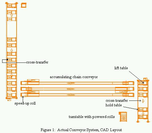
The example model is a small portion of a large body shop simulation built for an automobile manufacturer. Although small in scale, this example demonstrates some of the components mentioned above. Figure 1 depicts a CAD layout of the portion of the body shop, including three accumulating chain conveyors, two cross transfer conveyors, and several lift and hold tables.
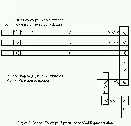
AutoMod has detailed built-in constructs for modeling conveyors. The CAD drawing of the layout is imported into AutoMod as a static background and a conveyor system is superimposed upon it. Figure 2 displays the conveyor system used for this portion of the system. As Figure 2 shows, to capture the details of transfers between equipment running at different speeds, smaller conveyor pieces were slightly extended over the gaps between the actual conveyors. An “X” represents locations where loads stop and/or either set or reset clear switches. Also, the speed-up sections on chain conveyors are represented as separate conveyor pieces appended to the end/tail of conveyor segments. Furthermore, multiple stations were defined to represent the locations where the speed of a pallet changes. The stations in AutoMod are defined with a load alignment attribute that determines when a load is considered to be at that location. For example, if a station has a “trailing edge” alignment, then the load will be considered to have arrived at that station when the trailing edge of the load reaches it. Consequently, travel speeds and distances can be accurately captured in the model by appropriately laying out stations and selecting their alignment attributes accordingly.
The lift tables interfacing with conveyor segments are represented as smaller conveyor sections attached directly to the end of a chain conveyor segment. The cross transfer conveyors are also represented as separate conveyor segments laid atop the segments that represent lift/hold tables. To model transitions between lift/hold tables and the cross transfer conveyors, two stations are created at the same coordinates. One of the stations is then attached to the conveyor segment that represents the hold/lift table; the other, to the conveyor segment representing the cross transfer line. Then, by using the “move” command at appropriate points, the load representing the pallet is instantaneously transferred from one segment to the other, displaying a smooth movement in animation. The time delays in lowering and raising the load to/from the chain are explicitly represented in the model by using the “wait” command.
Clear limit switches are represented in the model as conveyor stations. Once a load reaches a station representing a clear switch, it releases a resource that corresponds to the area that the switch controls. Clearly, most of those stations have a “trailing edge” alignment. Loads trying to enter the area wait to capture the resource and start moving as soon as the previous pallet clears the area. For each lift table and each hold table, there is a corresponding resource in the model.
5 ANALYSIS AND RESULTS OF AUTOMOD EXAMPLE
The complete simulation model of the body shop contained many more conveyors, processing times at stations, and downtimes associated with processes and some of the material handling equipment. Analysis of this model was conveniently undertaken with AutoStat. AutoStat, working in conjunction with AutoMod, provides determination of initial transients, management of scenarios as a database, and a “Design of Experiments” feature (Rohrer 1994b).
Analyses performed with the base model indicated that the system as designed could not meet the target production. Detailed analyses showed that the portion of the system shown in Figure 1 was one of several problem areas. Part of the problem was due to the distance between the first and second lift tables on the cross transfer (right side of drawing). As indicated earlier, on a cross transfer conveyor, pallets do not move until the next lift/hold table is cleared by the previous pallet. In this case, because of the long distance, each pallet experienced a delay exceeding the maximum allowable cycle time. The problem was remedied by placing a clear limit switch at a distance sufficiently removed from the lift table to avoid collisions. Consequently, the cycle time at the table was considerably reduced, thereby increasing the throughput.
Another part of the problem was due to the flow of pallets through the area. Normal flow of pallets required that the pallets go up on the cross transfer to the first conveyor, and proceed to the cross transfer (right side of Figure 1). The top two conveyors were to be used as temporary storage only when the pallets could not be sent (e.g., due to equipment down time) to the next set of conveyors that are beyond the top part of the drawing. However, simulations showed that the system would back up faster because once the first conveyor is blocked, there was no other way to utilize the middle conveyor for temporary storage. An alternative to this routing scheme was to send the pallets to the last conveyor at the top of the surge as the normal flow and then to accumulate pallets on the bottom two conveyors. Again, the model runs showed that this routing scheme worked better than the original and improved the overall throughput of the system.
Similarly, the complete model helped to identify several other problems with the conveyor system. By facilitating quick evaluation of the alternatives, the simulation model not only played a significant role in the detailed design of the system, but also provided quantitative support for managerial capital-investment decisions constrained by a tight project timetable.
In all these ways, results from micromodeling of conveyors, when included in macromodels of the production system, helped assess the degree to which material handling improvements spawned improvements in overall system performance.
6 SUMMARY
Particularly at the micromodeling level of detail, the accurate representation of conveyors and the equipment interfacing with them comprises numerous challenges. Meeting these challenges requires close attention to operational specifications and detail of the equipment, plus keen awareness of the capabilities of the simulation modeling tool chosen for use. This paper surveys these challenges and specific examples of them pertinent to a model including chain conveyors, cross transfer conveyors, lift and hold tables, and clear switches.
ACKNOWLEDGMENTS
Dr. Onur M. Ülgen, Professor, Department of Industrial & Systems Engineering, University of Michigan – Dearborn, and president, Production Modeling Corporation, has made valuable suggestions helpful to the presentation, organization, and clarity of this paper. Additionally, the cogent criticisms of two anonymous referees were especially helpful in these regards.
A preliminary version of this paper was presented at the June 1996 AutoSimulations annual users’ group meeting (AutoSimulations Symposium ’96 Mountain Rendezvous Proceedings, pages 313-319).
APPENDIX: TRADEMARKS
AutoMod and AutoStat are registered trademarks of AutoSimulations, Incorporated.
REFERENCES
Allegri, Theodore H., Sr. 1992. Materials Handling Principles and Practice. Malabar, Florida: Krieger Publishing Company.
Backers, R., and H. Steffens. 1983. Development of Strategies for Controlling Automated Material Flow Systems. In Proceedings of the 1st International Conference on Automated Materials Handling, ed. R. H. Hollier, 9-20.
Cahill, James M. 1985. Package-Handling Conveyors. In Materials Handling Handbook, 2d ed, ed. Raymond A. Kulwiec, 317-339. New York, New York: John Wiley & Sons, Incorporated.
Cerda, Carlos B. Ramírez. 1995. Performance Evaluation of an Automated Material Handling System for a Machining Line Using Simulation. In Proceedings of the 1995 Winter Simulation Conference, eds. Christos Alexopoulos, Keebom Kang, William R. Lilegdon, and David Goldsman, 881-888.
Foote, Bobbie L., A. Ravindran, Adedeji B. Badiru, Lawrence M. Leemis, and Larry M. Williams. 1988. Simulation and Network Analysis Pay Off in Conveyor System Design. Industrial Engineering 20(6):48-53.
Good, George L., and J. Thomas Bauner. 1984. On the Use of Simulation in the Design and Installation of a Power and Free Conveyor System. In Proceedings of the 1984 Winter Simulation Conference, eds. Sallie Sheppard, Udo W. Pooch, and C. Dennis Pegden, 425-428.
Gould, Les. 1993. Application Guidelines for Accumulation Conveyors. Modern Materials Handling 48(5):42-43.
Gould, Les. 1994. Conveyors Designed to Handle Small Products with Ease. Modern Materials Handling 49(3):44-45.
Graehl, David W. 1992. Insights into Carrier Control: a Simulation of a Power and Free Conveyor Through an Automotive Paint Shop. In Proceedings of the 1992 Winter Simulation Conference, eds. James J. Swain, David Goldsman, Robert C. Crain, and James R. Wilson, 925-932.
Henriksen, James O., and Thomas J. Schriber. 1986. Simplified Approaches to Modeling Accumulating and Nonaccumulating Conveyor Systems. In Proceedings of the 1986 Winter Simulation Conference, eds. James R. Wilson, James O. Henriksen, and Stephen D. Roberts, 575-593.
Hopings, Donald B. 1988. Simulation of Discrete Conveyor Systems. In Proceedings of the 1988 Winter Simulation Conference, eds. Michael A. Abrams, Peter L. Haigh, and John C. Comfort, 575-582.
Hudson, Wilbur G. 1954. Conveyors and Related Equipment, 3d ed. New York, New York: John Wiley & Sons, Incorporated.
K. W. Tunnell Company, Incorporated. 1995. Containerization. In Standard Handbook of Plant Engineering, 2d ed., ed. Robert C. Rosaler, 8-308-46. New York, New York: McGraw-Hill, Incorporated.
Laughery, K. Ronald. 1995. A Micro Saint Model of Conveyor Management Strategies. In Proceedings of the 1995 Winter Simulation Conference, eds. Christos Alexopoulos, Keebom Kang, William R. Lilegdon, and David Goldsman, 818-822.
Law, Averill M., and Michael G. McComas. 1991. Secrets of Successful Simulation Studies. In Proceedings of the 1991 Winter Simulation Conference, eds. Barry L. Nelson, W. David Kelton, and Gordon M. Clark, 21-27.
Muth, Eginhard J., and John A. White. 1979. Conveyor Theory: a Survey. AIIE Transactions 11(4):270-277.
Rohrer, Matthew. 1994a. AutoMod. In Proceedings of the 1994 Winter Simulation Conference, eds. Jeffrey D. Tew, Mani S. Manivannan, Deborah A. Sadowski, and Andrew F. Seila, 487-492.
Rohrer, Matthew. 1994b. AutoStat. In Proceedings of the 1994 Winter Simulation Conference, eds. Jeffrey D. Tew, Mani S. Manivannan, Deborah A. Sadowski, and Andrew F. Seila, 493-495.
Ruch, Stéphane, and Patrick Kellert. 1995. Validation of Manufacturing Systems Conceptual Models. In Proceedings of the 1995 Summer Computer Simulation Conference, eds. Tuncer I. Ören and Louis G. Birta, 400-406.
Sims, E. Ralph, Jr. 1992. Conveyors Are Often Taken for Granted by Material Handling Planners. Industrial Engineering 24(3):39-42.
Sule, D. R. 1988. Manufacturing Facilities Location, Planning, and Design. Boston, Massachusetts: PWS-KENT Publishing Company.
Tompkins, James A., and John A. White. 1984. Facilities Planning. New York, New York: John Wiley & Sons, Incorporated.
Tsai, Li-Hui. 1995. Mixed-model Sequencing to Minimize Utility Work and the Risk of Conveyor Stoppage. Management Science 41(3):485-495.
Ülgen, Onur M., John Shore, and Eric S. Grajo. 1994. The Role of Macro- and Micro-Level Simulation Models in Throughput Analysis. Paper presented at 1994 ORSA/TIMS Joint National Meeting, 23-26 October, Detroit, Michigan.
Ülgen, Onur M., and Sanjay S. Upendram. 1995. The Role of Simulation in Design of Material Handling Systems. In AUTOFACT Conference Proceedings Volume 1, ed. Lisa Moody, 259-273.
Witt, Clyde E. 1995. Powered Roller Conveyors: Sound Engineering Creates Better Environment. Material Handling Engineering 50(13):41-46.
AUTHOR BIOGRAPHIES
ALI K. GUNAL is a Systems Consultant at Production Modeling Corporation. He received his Ph.D. degree in Industrial Engineering from Texas Tech University in 1991. Prior to joining PMC, he worked as an Operations Research Specialist for the State of Washington, where he developed a simulation system for modeling and analysis of civil lawsuit litigation. At PMC, he is involved in consulting services for the analysis of manufacturing systems using simulation and other Industrial Engineering tools. He is familiar with several simulation systems including AutoMod, ARENA, QUEST, ROBCAD, and IGRIP. He is a member of the Institute for Operations Research and the Management Sciences [INFORMS], the Institute of Industrial Engineers [IIE], and the Society of Manufacturing Engineers [SME].
SHIGERU SADAKANE holds a bachelor’s degree in Industrial & Systems Engineering (University of Michigan – Dearborn, 1994). He is an Applications Engineer at Production Modeling Corporation, and highly familiar with simulation and facilities-layout optimization systems including AutoMod, WITNESS, LayOPT, QUEST, IGRIP, and SIMAN. He is a member of the Institute of Industrial Engineers [IIE] and the Society of Manufacturing Engineers [SME].
EDWARD J. WILLIAMS holds bachelor’s and master’s degrees in mathematics (Michigan State University, 1967; University of Wisconsin, 1968). From 1969 to 1971, he did statistical programming and analysis of biomedical data at Walter Reed Army Hospital, Washington, D.C. He joined Ford in 1972, where he works as a computer software analyst supporting statistical and simulation software. Since 1980, he has taught evening classes at the University of Michigan, including both undergraduate and graduate simulation classes using GPSS/H, SLAM II, or SIMAN. He is a member of the Association for Computing Machinery [ACM] and its Special Interest Group in Simulation [SIGSIM], the Institute of Electrical and Electronics Engineers [IEEE], the Society for Computer Simulation [SCS], and the Society of Manufacturing Engineers [SME]. He serves on the editorial board of the International Journal of Industrial Engineering – Applications and Practice.
danielg
You may also like

La tecnología de los Gemelos Digitales en el futuro de los eventos deportivos y de entretenimiento
Veronica Kerr | February 16, 2023

PMC White Paper | Simulation Of Medical Laboratory Operations To Achieve Optimal Resource Allocation
danielg | January 18, 2023
PMC White Paper | Simulation Increases Efficiency Of Engine Air-Leak Testing
danielg | January 18, 2023
PMC White Paper | Simulation Helps Assess and Increase Airplane Manufacturing Capacity
danielg | January 16, 2023
